

Pattern, Tradition and Innovation in Vernacular Architecture
Arthur J. Lawton
Introduction
By mid-nineteenth century, architecture’s inherited practices of past geometrical design and lay-out were being forgotten, largely due to improved general literacy and calculating skills and the advent of aids like the retractable tape measure and blueprints. As practical interest in geometry was disappearing, academic interest in geometry developed as a source of beauty, efforts that sought to identify basic principles of harmony and beauty. Early architectural historians sought the Golden Section, the Fibonacci series, square root of two, the triangle, square, pentagon, hexagon or octagon as governing principles of floor plans. They attributed philosophical, religious or folkloric significance to them rather than demonstrating them as practical steps that create plans and buildings. This methodology sought geometrical figures embedded in the plan by superimposing the favored element on plans to identifying coincident points between diagram and plan lines.
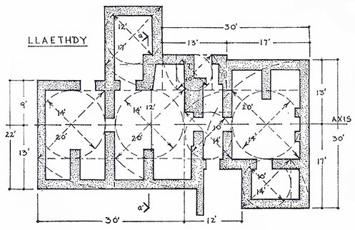
Figure 1. Jenkin’s analysis; rotating the diagonals of an assemblage of squares that circumscribe circles.
Recent analysis turned to geometry’s practical role in lay-out practices. In 1967 J. Marshall Jenkins examined Welsh vernacular ground lines, noting that from a circle one can easily construct a square whose side length equals the circle’s diameter.1 On this basis he suggested square and circle were the earliest instruments regulating building construction (Figure 1). His analytical method rotated the square’s diagonal to one of its sides to create a 1 : √2 rectangle. Jay Hambidge called these figures root rectangles in his earlier work on geometry and design.2
While Jenkins accounts for all rectangular components of the Llaethdy floor plan, this analysis is an assemblage of multiple adjacent units lacking whole system unity. However, from this work the present author’s research began, seeking an organically unified plan-development system, functionally effective regardless of the following limitations that shaped pre-modern construction practices; 1. minimal to non-existent calculating skills, 2. lack of the numerically graduated tape measure, 3. restricted durability and size of portable drawing surfaces, 4. information transmission from design to construction by template, 5. identical geometrical steps by divider and straightedge or cord and peg. Given vastly different pre-modern methodologies we are well advised to follow Henry Glassie’s advice to seek “an account not of how a house is made, but how a house is thought.”3
Two practices enable thinking a house without detailed measured drawings. First, proportionally related sequential steps constitute an inter-related system wherein all subsequent steps are governed by information contained in the previous step. Secondly, identical divider-straightedge steps and cord-peg steps enables calculation-free scale change between design and construction. Scholars have raised a critical question on each issue.
Arguing that large construction processes were governed by modular grid and referring to the grid-like geometrical pattern in the twelfth century illumination The Dream of Gunzo, Konrad Hecht, asked
“If the miniature does in fact render a proportional pattern, what would the proportional pattern be that exists as some parallel and some rectilinear lines”?
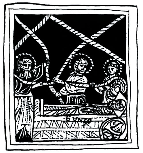
Figure 2. Gunzo dreams the plan for Cluny, (Paris, Bibliothéque Nationale MS lat.17716, fol. 43
Above Gunzo (Figure 2), Saints Peter, Paul, and Stephen uncoil long cords in a network revealing the ground plans Gunzo must convey to Abbot Hugh.” Hecht argued then that modular measurement governed the lay-out, not geometry. On the other hand John Harvey argued for geometry in The Medieval Architect,
“So far as there is direct surviving evidence for systems of medeval proportion, it indicates that they were the result of direct use of geometrical methods, and never involved calculation. Arithmet cal and algebraic functions are there, but they went unrecognized by the craftsmen who reached their objective by a different road.”4
In The Wise Masterbuilder Nigel Hiscock pointed toward a key question regarding scale transformation from design to construction.
“Although the documentary evidence shows that the designing of a plan on parchment and laying it out on site both depended on the employment of geometry, the precise connection between design and dimension remains elusive.”5
Plan-net analysis, proposed as a hypothesis, brings together Konrad Hecht’s ‘proportional pattern that exists as some parallel and some rectilinear lines’ and Hiscock’s elusive connection between design and dimension. Answering Hecht, plan-net analysis extracts a network of parallel and rectilinear lines from an initial square base figure, that in answer to Hiscock, is done without calculation through identical divider-straightedge and cord-peg steps. Plan-net lines and intersection nodes mark all plan features and identical geometrical steps transform scale from design to construction. Extracting from its initial base figure an accurate floor plan by means of a plan-net serves to validates the plan-net hypothesis.
Elements Contributing to Plan-Net Methodology
The plan-net as a tool is documented in the foundation texts of Egyptian temple foundations. Alexander Badawy noted they describe ceremonies to lay out ground lines in Ancient Egyptian Architectural Design: A Study of the Harmonic System. The house of Rattaoui, “...was loosened by means of the plan-net that was measured perfectly.”6 Geometry itself is a method of measurement. Badawy says the verb translated as “loosened” also means “unfurl” or “solve,” when marking the building axis or outline (Figure 3). The term “loosening” is made clear in an inscription referring to Thutmosis III, in whose hieroglyphic figures the Pharaoh personally performs a double ceremony, each phase described individually and in differing language.

Figure 3. Thutmosis III, “The King himself...spreading out the plan-net, putting it on the ground.”
“The king himself, who performed with his two hands the stretching of the cord and the spreading out of the plan-net, putting it on the ground.”7
Badawy believed the first phase, cord extension, plotted the building axis or marked its outline. Based on the second part I suggest the first phase plotted the axis, ritually orienting the plan-net and the second phase staked out the ground lines using the plan-net, w3wt, a word etymologically related, to w3w3 meaning “to plan” or “to project,” and to w3t, meaning “cord.” He continues,
“The scene described by this text usually features the king facing Seshat, the goddess of architecture and reckoning, both driving a tall stake in the ground. A cord is wound around both stakes as a symbol for the plan-net. Some texts define the striking of the nbi stake: He spread out the plan-net, the nbi stake, being in his hand.”8
Badawy discussed other texts in which width was determined proportionally to the length by an archived geometrical rule. A text from Dendera says: “Its length is exact, its width according to the formula ( ds, d3js), its norm is in excellent work.”9 He suggested that “loosening” or “solving” implied by the term wh‘ indicated that Pharaoh and priest outlined the building and staff determined inner divisions from plans. I propose that casting the plan-net both marked the outline and position of all internal major elements. Badawy noted that the Pharaoh kept a close eye on ritually significant works,
“King Sahure followed the progress of the work on two stelae for the audience hall ‘to be done in the presence of the king himself,’ and that ‘every day’ his majesty had ‘color’ put on them and had them painted in blue...”10
From the New Kingdom several records describe the interest of King Thutmosis III in foundation ceremonies.
“My majesty ordered that the foundation ceremony should be prepared (at the approach of) the day of the Feast of the New Moon, to spread out the plan-net upon this monument....This god (meaning in this case the Pharaoh) assumed the station (for) the spreading out of the plan-net...Behold the majesty of this revered god desired to do the extending of the cord himself.”11
Plan-net analysis speaks to the design problem, marking both the exterior building outline and internal plan details and to the non-calculated change of scale problem, manipulating geometrical constructions rather than numbers.
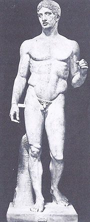
To govern a creative process shaping physical material, the Greek sculptor Polykleitos developed a sequentially proportional systematic canon to extract the whole human form in correct proportions from a single base figure (Figure 4). Richard Tobin reconstructed the process and tested it on the Doryphoros statue in figure four, each new step generated from information contained in the previous step.12
All steps manipulate geometrical figures rather than numbers.
The base figure is a square the length and width of the distal phalange of the little finger. Its diagonals rotated to one side transform the square to a 1 : √2 root rectangle. In Figure 5 this rectangular figure marks the width and length of the adjacent medial phalange. Rotating the medial diagonal proportions the proximal phalange and similarly from there to the wrist, from wrist to elbow and from elbow to shoulder top. Each new step advances the diagonal’s pivot point.
Figure 4. The Doryphoros statue by Polykleitos. (The National Museum, Naples.)
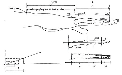
Figure 5. The canon of Polykleitos applied to the forearm. (Drawing by Richard Tobin)
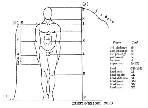
Figure 6. The canon of Polykleitos applied to the whole body. (Drawing by Richard Tobin)
For the main body the diagonal’s pivot point in figure six remains the same (Figure 6). The head to clavicle diagonal extends from the head to the nipple, the head to nipple diagonal extends to the groin, from head to groin to the knee, and from head to knee extends to the soles of the feet. From finger to shoulder the pivot point advances with each segment. From head to foot it remains in one place. Tobin’s sequentially proportional reconstruction manipulates geometrical forms, organizing the completed work as a unified whole. Method variation in determining pivot point allows some freedom within the proportional system. He demonstrated extraction of the dimensions and proportional relationships for all elements of a completed sculptural figure from an initial base figure.
Such methods from the ancient world were not forgotten in the later pre-modern world. They were elaborated and appear in part in the textual record in the 1486 publication of Büchlein der Fialen Gerechtigkeit (Booklet Concerning pinnacle Correctitude) by Matthes Roriczer. Lon Shelby noted in his study of Roriczer’s work that,
“The medieval manuscripts by or about masons generally have a theme running through them that clearly establishes the ‘art of geometry’ (frey Kunst der Geometry) as fundamental in producing what Matthes Roriczer called ‘drawn-out stonework’ (ausgezoge Steinwerk)...”13
Medieval masons solved stereotomical problems “primarily through the physical manipulation of geometrical forms by means of the instruments and tools available to the masons.” He called this constructive geometry, the construction and manipulation of simple geometrical forms using rule-of-thumb procedures followed step by step with virtually no mathematical calculations.14 They extracted the “right” form out of the base figure, as Roriczer says in his booklet, Büchlein von der Fialen Gerechtigkeit,
“I have tried ... to explain the beginning of drawn-out stonework – how and in what manner it arises out of the fundamentals of geometry through manipulation of the dividers, and (how it) should be brought into the correct proportions – and to draw these hereafter-mentioned forms...”15
Roriczer clarifies that his work was the ‘beginning’ of drawn out stone work, not the full story. The 1459 Regensburg Masons’ Ordinances prohibited anyone from doing mason’s work who failed to how to “take the measure (Mass) or the extrapolation device (Auszug) out of the base plan (Grund),” that is, “extracting” it from the base figure. We turn now to how the base figure is developed and how to extract the elevation from the base figure.

Figure 7. Roriczer’s first three steps construct three nested and proportionally related squares. From Roriczer’s Büchlein von der Fialen Gerechtigkeit.
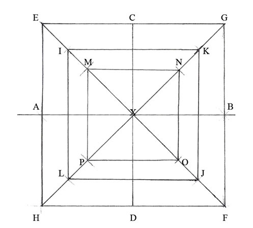
Figure 8. How to draw the nested squares in parallel with each other. (Drawing by the author)
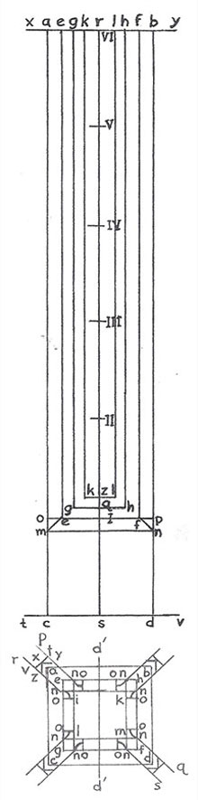
Roriczer begins with three concentric squares that are proportionally related (Figure 7). Points g,e,h and f, and points i,k,m and l are easily constructed center points of their respective lines, but how to construct them in parallel for base figure he does not explain (Figure 8). As constructed by the author figure eight shows three parallel squares in the same proportional relationship (Figure 9). In figure nine, the nested squares are elaborated into the base figure to extract the pinnacle that consists of the body, the cap and the finial. Figure 10 illustrates extraction of the pinnacle body. The extraction device is the central vertical line divided into six equal segments marked I to VI above the square base figure below. Base figure intervals are copied directly onto the horizontal top and bottom lines of the extraction device. Similar steps extract the cap and the finial from the base figure.
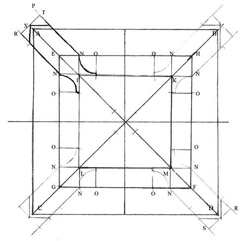
Figure 9. The completed base figure from which the extrapolation device will extract the elevation. Drawing by the author.
Egyptian foundation texts identify the plan-net as methodology and Gunzo’s dream miniature suggests a working plan-net. Polykleitos used sequential proportionality and the root rectangle to extract all human body proportions from a square base figure. Roriczer explained more elaborate constructional geometry solutions for architectural design problems. The Sulva Sutras demonstrate cord and peg use to solve problems of architectural lay-out.
Method and Application of Plan-Net Analysis
In Figure 11 an early nineteenth century French book on the first degree of Freemasonry displays the tools necessary for plan-net analysis. Within the Pharoah’s cord are divider and square, Gunzo’s network of cords and on the tablet left of the straightedge a square defined by two pairs of intersecting parallel lines. This square merits our full attention as it is the base figure for plan-net analysis.
Figure 10. Dimensions copied from the base figure onto lines TSV and XRY set The Sulva Sutras (sutras of the cord) of seventh century Vedic India describe the use of constructional geometry by cord and peg to lay out altars with the precision required by ritual. Altars were all composed of the same number of bricks but constructed in a wide variety of shapes. Sutra technicians worked with circle, triangle and square figures, used cord and peg methods of constructive geometry to assure ritual exactness of size between variously shaped altars.16
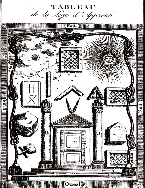
Figure 11. Set of Masonic symbols from an eighteenth century French Masonic handbook.
The square in figure twelve contains two diagonals, both longer than the sides by 1 : √2 (Figure 12). To expand the square into plan-net, rotate these diagonals from their corner pivot points to superimpose them on the square’s sides. At the end-points of the diagonals, mark a new line perpendicular to the side lines to form a root rectangle (Figure 13). In subsequent steps diagonal pairs of any existing rectangle may be rotated, resulting in a growing cascade of new intersection nodes, each additional node a potential starting point for the next step.
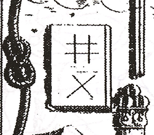
Figure 12. The basic figure of plan-net analysis preserved in Masonic symbolism.
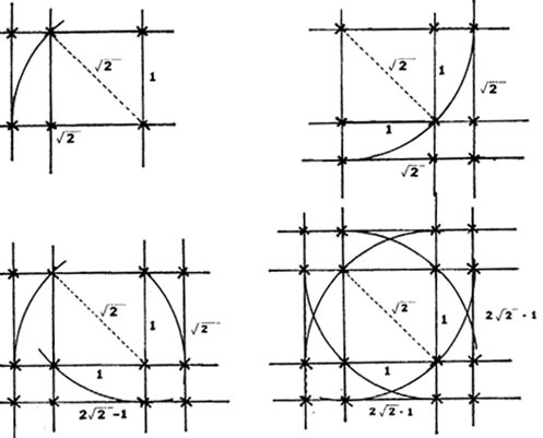
Figure 13. Expanding the plan-net by selecting intersection nodes as pivot points for new quadrangles.
How then does one get from initial square base figure to complete floor plan? The ca. 1745 Bertolet House in Berks County, Pennsylvania is a Germanic three-room central fireplace log house (Figure 14).17 The analysis begins in figure fifteen where square ABCD marks the fireplace width, one jamb inside line DC and the other outside line AB. AD marks the staircase edge (Figure 15). Rotating diagonal BD to E marks the front wall with the front door at ½ DC. Diagonal BD to F marks the left gable wall. From a new and larger rectangle corner, diagonal GB to H marks the staircase turn at the landing and GI to J marks the rear wall, with the rear door at ½ AB. Again from G, diagonal GK to L marks front and rear windows. Diagonal MN to O marks the right gable wall.
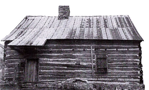
Figure 14.The ca. 1745 Bertolet house in Berks County, Pennsylvania.
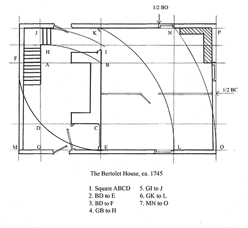
Figure 15.Four plan-net analysis steps mark out the Bertolet House floor plan.
The lateral central partition on the right side centers neither on the fireplace back wall nor the right gable wall, but is precisely at ½ of side BC of the square ABCD. Perhaps coincidence, but since all significant plan elements are marked by plan-net lines or nodes, it is plausible that square ABCD was in fact the beginning figure in plan development. Analytical characteristics frequent for this house type are; 1. The initial square defines fireplace location and size. 2. Plan development begins by completely developing the kitchen area. 3. The transverse gable length is determined prior to the lateral length. 4. Transverse development and lateral development are separate stages. 5. The systematic proportions of root rectangles unify the Bertolet plan throughout the whole.18
This flexible and simple method is suitable to a small one and a half story log house at the point of initial settlement or the two story stone house with double attic of a well to do community leader such as Henrich Antes. Though the proportions differ somewhat, his floor plan is the same three-room central fireplace plan (Figure 16). What is different is social position and economic means and a slight variation of the steps taken. Like the Bertolet house, the square ABCD defines the fireplace and marks the front and rear door (Figure 17). Added steps make the developed kitchen area wider and mark the full transverse axis. Antes’ variation occurs in the following development of the lateral axis.
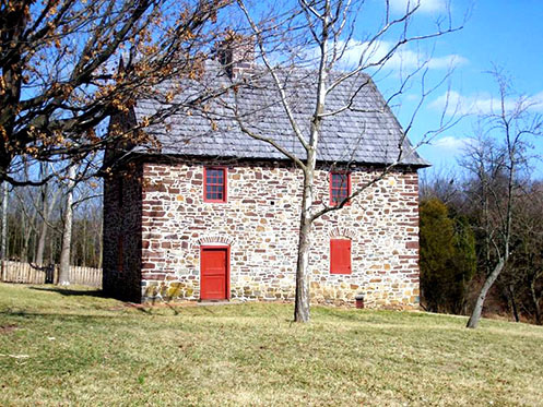
Figure 16. The 1736 home of Henrich Antes, an immigrant Bürger from the Kleinstadt of Freinsheim in the Rhenish Palatinate.
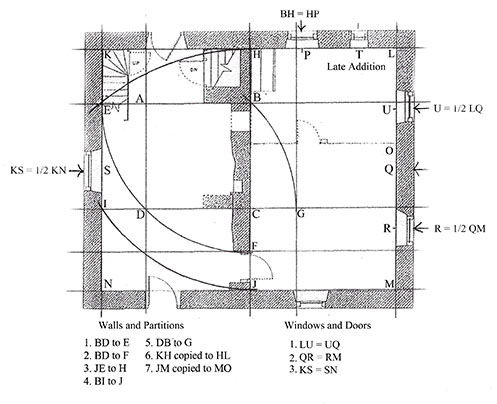
Figure 17. Antes floor plan; asymmetrical three-room plan and off-center hearth location flanked by symmetrical gables, with right and left halves balanced across centerline HJ.
Square ABCD marks three fireplace walls, the front door and the rear door. BD to E marks the left gable wall and BD to F marks a break in the firewall where in the Bertolet house it marked the front wall. JE to H marks the rear wall and BI to J the front wall. DB to G marks line GP for the front parlor window and the lateral partition door. Then Antes broke with Bertolet’s pattern. Antes copied interval KH to HM to mark the right gable, making HJ the transverse center line, producing a more square design consistent with houses of his Bürger neighbors in Freinsheim, Germany. Interval JM copied to MO marks the partition between front and back rooms, resulting in a square parlor. Wall and partition positions are now complete. Window and door details are either aligned to the plan-net lines or are at intervals between those lines as copied from adjacent locations. BH copied at right angles to HP marks the single original rear window. The small window to the right is a later addition. The window at U is ½ LQ and the window at R is ½ QM. The single front window is at line PG, the front and back doors are at line AD and the left gable window is at ½ KN.
Plan-net lines for exterior walls are inside the walls. On the right gable, window center points neatly quarter line LM. Measured from the outside gable corners these window centers have no unit of measurement common to outside corners and all window centers, suggesting plan-net lines KL and NM played a role in lay-out. For the window at P, there is no rational for division any interval by halves or quarters, but rotating BH to HP fits conveniently.
This analysis renders visible certain elements suggesting transition. The facade, the off-center hearth and the three-room plan are asymmetrical and reproduce exactly the identifying features of both the Bertolet house and the traditional plan by Richard Weiss seen in Figure 18. However, the Antes centerline HJ divides the plan into two evenly balanced halves, the left gable window is centered on the gable wall and the right gable windows are equidistant from the both corners and the lateral center line, all indicators of symmetry.
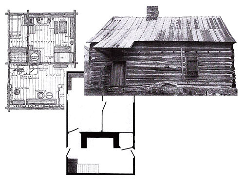
Figure 18. The Bertolet house stands in the Germanic asymmetrical three-room central fireplace tradition, an exact copy of the Swiss form presented by Richard Weiss. View this image larger.
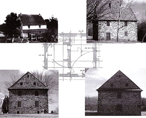
Figure 19. Antes’ asymmetrical plan and façade flanked by symmetrical gables communicate both his upper-class position and his connection to tradition. View this image larger.
Figure eighteen presents the Bertolet builder as a conservative agent of vernacular, architectural tradition. Adapting proportions to meet personal needs and resources, his plan is very conservative (Figure 19). Henry Antes was an active social agent, in Pennsylvania a Justice of the King’s Peace, a beloved and respected religious leader and highly competent millwright. Given his position, it isn’t surprising to see the traditionally asymmetrical facade and floor plan sandwiched between two symmetrically organized gables hinting of Pennsylvania Georgian symmetry. The interior plan symmetrically balances three asymmetrical rooms across a central fire wall. That Bertolet and Antes actually used plan-net design methods is unproven, but using plan-net analysis to tease out pattern embedded in floor plans provides a new perspective. Correlating plan-net and sociocultural pattern identifies innovative uses of stable traditional methods, communicating social position to the immediate community and effecting change in architectural pattern over the long term.
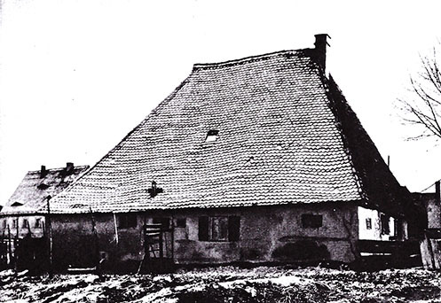
Figure 20. Haus Hulscher, 33 Bucherstrasse, Thon, circa 1930. Photo by Rudolf Helm.
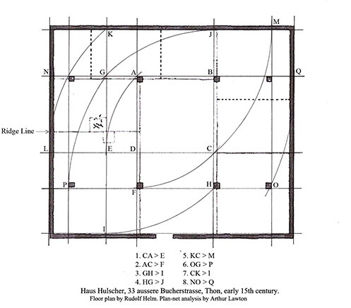
Figure 21. Dotted lines show partitions in the Helm plan that do not conform to plan-net lines. Hans Hulscher house, aussere Bucherstrasse 33,Thon.
Pattern rendered apparent through plan-net analysis can contribute to interpreting the architectural fabric of a building (Figure 20). In the 1930s Rudolf Helm photographed and drew the floor plan of a Schwedenhaus in Thon, near Nürnberg, a German house form shon in figure twenty and dating from the fifteenth century.19 Elements of this house such as the kitchen hearth and the parlor heating oven, separated by a fire wall, adhere to tradition and are clearly original. The massive roof seen in figure twenty is supported not by the low walls but by the eight posts in Figure 21. The analysis marks the four exterior walls, the hearth location and the arrangement of posts. Some partitions fall precisely on these lines, but Helm indicated with dotted lines three partitions incompatible with the Schwedenhaus tradition and whose origin is indeterminate from the building fabric. Not falling on plan-net lines, analysis suggests these three partitions are later alterations. Figure 22 is the proposed original floor plan based on this analysis. Its pattern of spatial division and use corresponds to his many fifteenth and sixteenth century houses plans from Nürnberg.
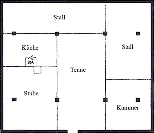
Figure 22. Reconstructed floor plan based on plan-net analysis, retaining only partitions aligned with plan-net lines. Hans Hulscher house, aussere Bucherstrasse 33, Thon.
Plan-net analysis alone does not directly document use of the method for pre-modern design and layout. It does however provide insight into a deeper basis for design, and contributes to interpreting a building’s fabric.
Endnotes
1 J. Marshall Jenkins, “Ground-rules of Welsh Houses: A primary Analysis,” Journal of The Society for Folk Life Studies, 5, (1967). 69-91.
2 Jay Hambidge. The Parthenon and other Greek Temples. Their Dynamic Symmetry, (New Haven: Yale University Press, 1924). 129.
3 Henry Glassie. Folk Housing in Middle Virginia. (Knoxville: The University of Virginia Press, 1975). 21.
4 John Harvey. The Medieval Architect. London: Wayland Publishers, 1972. 98.
5 Nigel Hiscock, The Wise Masterbuilder. Brookfield: Ashgate Publishing Company Ltd., 2000. 278.
6 F. Daumas. Les Mammisis des Temples Egyptiens, (Paris: Soc. d’ed.”Les belles Lettres,” 1958.) 342.
7 Kurt Sethe. Urkunden des 18 Dynastie, I. (Leipzig: 1906. Also Breasted, Vol. II, ) 152.
8 Brugsch. Hieroglyphisch-Demotisches Wörterbuch der āegyptischen Sprache, I, (Leipzig: 1926). 249.
9 Badawy, 9.
10 Badawy, 11.
11 Badawy, 11.
12 For a full treatment of this proposal, see Richard Tobin. “The Canon of Polykleitos.” The American Journal of Archeology. Vol. 79, No. 4 (Oct., 1975), 307-321.
13 Lon Shelby. Gothic Design Techniques: The Fifteenth Century Design Booklets of Matthes Roriczer and Hanns Schuttermeyer. Carbondale: Southern Illinois University Press, 1977. 53.
14 Lon Shelby. “The Geometrical knowledge of Medieval Master Masons. Speculum, Vol. 47, No. 3 (July, 1972), 409.
15 Shelby. Gothic Design Techniques, 83.
16 For a detailed explanation of the Sulva Sutras with examples of problem-solving methodology, see G. Thibaut, Mathematics in the Making in Ancient India, ed. with an introduction by Debiprasad Chattopadhyaya, (Calcutta: K. P. Bagchi and Company, 1984). For a translation of the Sulva Sutra text, see D. P. Kularia, Kätyäna Śulnasütra with commentary, (New Delhi: Devesh publications, 2009).
17 For the three-room plan, please see Richard Weiss, Hauser und Landschaften der Schweitz, (Erlenbach-Zurich: Eugen Rentsch Verlag, 1959. ) 133-155.
18 Jay Hambidge. The Parthenon and Other Greek Temples: Their Dynamic Symmetry, (New Haven: Yale University Press, 1924). 129.
19 Rudolf Helm. Das Bauernhaus im Gebiet der freien Reichstadt Nürnberg, (Berlin: Herbert Stubenrauch Verlagsbuchhandlung, 1940) 53-55
Author Biography
Presently a PhD candidate at Indiana University, Bloomington, Indiana in the Department of Folklore and Ethnomusicology, Arthur J. Lawton lives in Tifton, Georgia. His dissertation examines the geometry and arithmetic of vernacular architectural design and layout. Additional research includes the life of Henrich Antes, an 18th century German millwright and Baumeister in Pennsylvania.